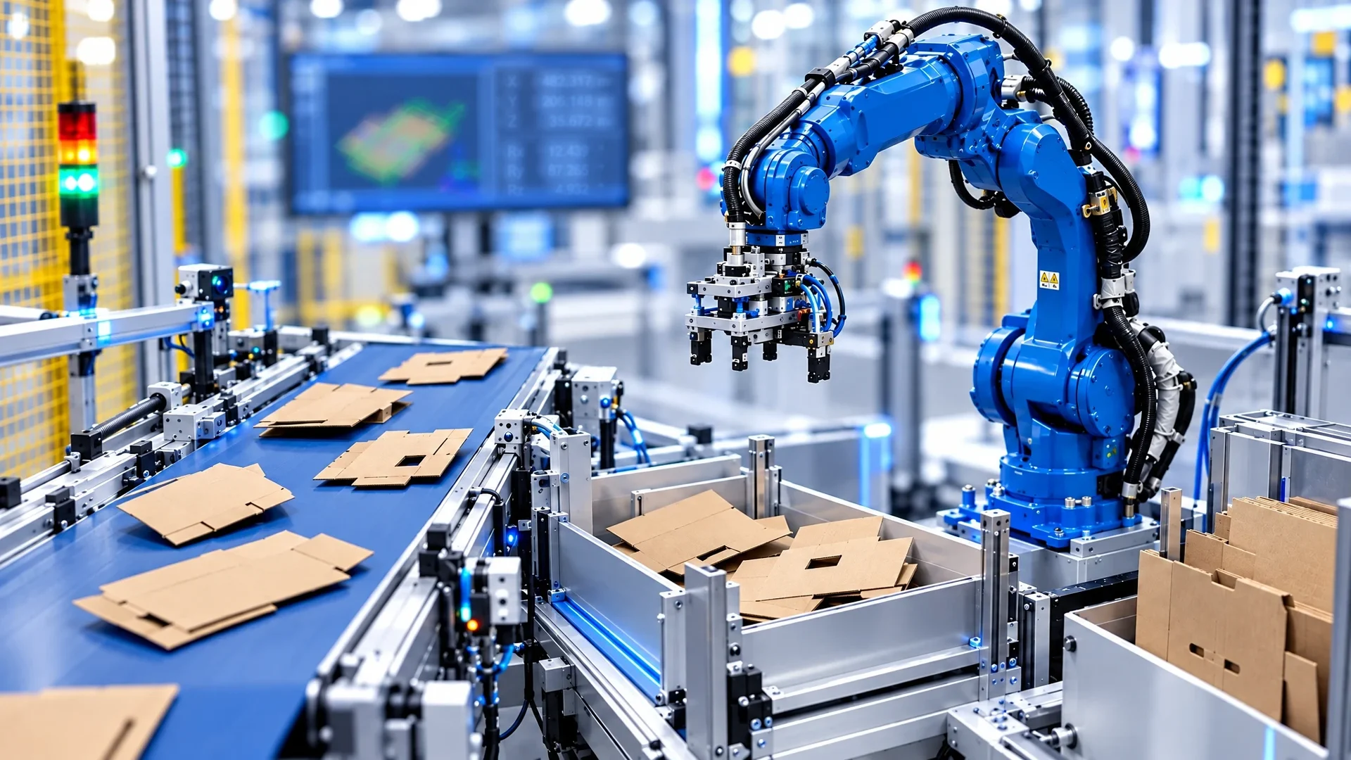
A robot only grips a cardboard part safely if it knows its position and angle of rotation. However, the parts do not arrive in alignment. They can be within 360° in any orientation. The position detection of cardboard parts must therefore not only clarify whether a part is there, but also where it is located and how it is turned. The result must then be available in a format that the robot controller can process directly.
Why a fixed search position is not enough
A sensor that only reports the presence of a part does not provide a position. An evaluation in a fixed image area also requires that the part always appears in the same orientation. Neither applies here. What is needed is image processing that finds a stored pattern even if it is twisted and converts the pixel values into millimeters.
Solution 1: weQube B50S104 with pattern matching
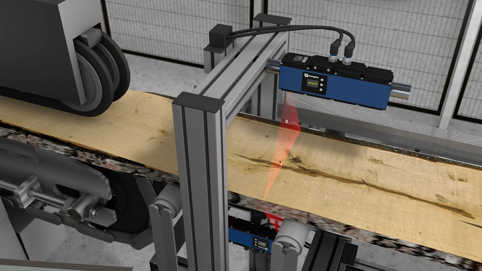
The weQube B50S104 and the uniVision software are used for the position detection of cardboard parts. The evaluation takes place in four steps:

- Image Acquisition: Recording of the image, on cardboard with the internal lighting.
- Pattern Match module: The pattern matching finds the cardboard part even in a rotated position and provides position and angle.
- Spreadsheet: The pixel values are converted into millimeters based on the working distance. In addition, the table formats the information from the pattern matching as the robot needs it.
- Output: Via the TCP device or the Industrial Ethernet device.
| Here, the conversion from pixels to millimeters is in the table module. It applies to the set working distance. If the distance changes, it must be adjusted. |
Solution 2: Smart Camera B60M102 with Calibration and Locator
The B60M102 goes the way of a real calibration:
- Image Acquisition
- Calibration module: Equalization of the lens and conversion from pixels to millimeters based on calibration plates.
- Locator module: Finds the cardboard part in the calibrated image.
- Spreadsheet: Formatting the information for the robot.
- Output: Also via TCP or Industrial Ethernet.
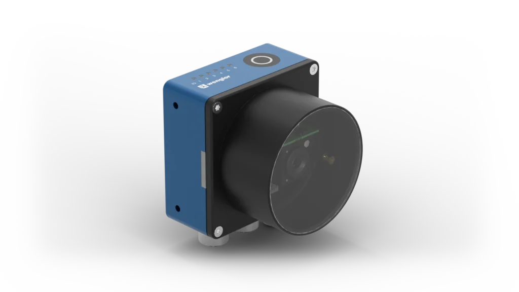
| The difference lies in the conversion: With the weQube, it is done via the known working distance in the table module, with the B60 via a separate calibration module that also takes into account the objective distortion. |
Connection, lighting and process monitoring
Both devices work with internal lighting. This works well on cardboard, as the matt surface is not very disturbing. The results are sent to the robot controller either via TCP or Industrial Ethernet. In addition, each device can output a visualization. This allows the operating personnel to follow the process and start another application for other parts in the event of a production change.
What to look out for in the design
Cardboard quality and print image
The pattern must offer sufficient contrast in the picture. This should be checked with the real parts.
Working distance and calibration
The conversion to millimeters is only as accurate as the working distance or calibration.
Part variants
A separate application is required for each type of part. It can be started when production is changed.
Conclusion: No angle, no position – no gripping
In the case of arbitrarily rotated cardboard parts, the evaluation of position and angle is decisive for the success of the robot handle. The weQube B50S104 solves this compactly via Pattern Match and a conversion in the table module. The B60M102 offers the way through a complete calibration with calibration plates and locator. Which variant fits depends on how the pixel-to-millimeter conversion is to be implemented in the setup. A test with real cardboard parts should secure the decision.